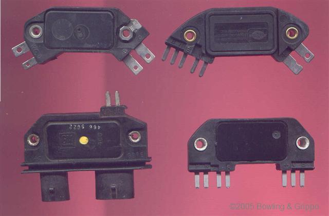
There were a number of different kinds of General Motors HEI modules:
When using the HEI-7 or HEI-8 pin modules, you need to set your MicroSquirt® controller to:
Parameter | Value |
| Ignition Input Capture | Rising Edge |
| Cranking trigger | Trigger Rise |
| Coil Charging Scheme | Standard Coil Charge |
| Spark Output | Going High (Inverted) |
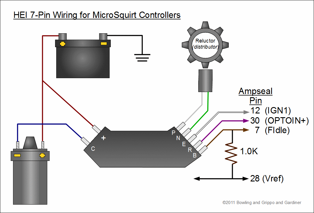
With a GM HEI 7-pin (and 8-pin modules), the ignition module wires you need to know about are:
The 4-pin HEI uses a negative-to-positive transition, while the 7/8-pin uses a positive-to-negative transition (though this *might* have changed in some applications). Thus polarity of the reluctor signal is critical to proper function.
In the GM 7/8-pin HEI, the module converts the AC signal from the variable reluctor pick-up {on pins P & N} in the distributor to a 'square wave' tach signal {on pin R} suitable for your MicroSquirt® controller. The falling edge of this square wave is used as the trigger event (which becomes the rising edge when the input circuit inverts the signal).
HEI does not use the reluctor for dwell control, this is accomplished in the module. Dwell needs to be independent of RPM. Variable reluctor output is RPM dependent with regard to both its width and amplitude of its output. The only thing constant with a variable reluctor output is the location of the zero crossing point with respect to the passing tooth.
Be sure to get the variable reluctor pick-up wires connected properly. Reversing the variable reluctor sensor wires and thus the polarity of the sensor causes the leading voltage to go negative first and the electronics ignores the positive going transition. Thus trigger signal, if ever recognized, is the falling edge of the voltage as the end of the tooth passes.
The only way to get proper triggering at the center of the tooth is to have the positive ½ cycle first (tooth approaching) and the negative ½ cycle last.
The 'trigger offset' in TunerStudioMS is the number of degrees before TDC at which the VR sensor output goes from positive to negative, and the falling edge of the square wave is sent from the 7/8-pin module to your MicroSquirt® controller. This tells your MicroSquirt® controller where the crankshaft is positioned so that timing advance can be calculated appropriately. (Note that since the optoisolator (U4) inverts the trigger signal, you specify 'Rising edge' for the 'Input Capture' in TunerStudioMS, which refers to the signal at the processor.) Positive trigger offsets are used to specify the number of degrees before top dead center (BTDC), negative numbers are used for triggers that occur after top dead center (ATDC).
The 7/8-pin HEI uses a "next cylinder" advance calculation method. That is, you get the square wave out of the module at (say) 10° BTDC which is used for cranking and limp home mode. To advance the timing your MicroSquirt® controller waits until the NEXT cylinder to fire to provided an altered signal to the coil.
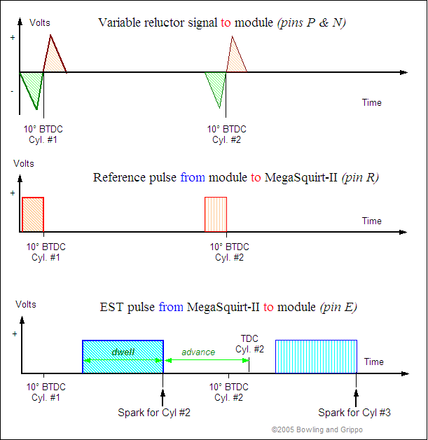
Reference (tach) pulses come into your MicroSquirt® controller from pin R at 10° BTDC (this offset can be calibrated using TunerStudioMSII so that the spark table values match the actual advance). At each reference pulse, the period between it and the previous reference pulse is calculated. The difference is used (with a time interpolation technique) to set up the timing pulse for the next ignition event. Specifically, the reference period is added to the time of the current pulse, a calculated amount subtracted for the advance, another amount subtracted for the dwell to determine the rise time.
When the signal is 'high', current flows. When the signal is pulled low, current stops, the magnetic field in the coil collapses, and a spark is produced. Thus, the HEI module fires on the 'trailing edge' of the advance signal. The advance signal is generated by your MicroSquirt® controller from the tach signal by modifying its duty cycle (pulse width). Larger duty cycles mean less advance, as the spark is delayed by a larger amount.
The ignition signal going to your MicroSquirt® controller comes from pin R of the 7-pin HEI module and goes to the Ampseal VR1IN+ pin 32. Leave the VR1IN- pin #33 unconnected (do not ground it).
The timing of the trailing edge determines the amount of advance: a longer pulse width means a more delayed, 'retarded' spark, while a shorter pulse width means an earlier 'advanced' spark.
In a GM vehicle, the override signal is zero volts during cranking (less than 400 rpm or 5 to 15 seconds), then there is 5 volts on this wire after the engine starts to signal the 7-pin module that it should use the signal on the white wire to control timing. You need to apply a 5 volt signal here in order to control the timing while running. A wire can be run from the 5 Vref for the TPS (Pin 28 on the Ampseal connector) to the HEI pin B through a relay that is switch from a source that is hot in RUN but not CRANK (see the diagram below). Most cars have a source like this, check your service manual.
Alternatively, you can use the spare port settings to send a 5 Volt signal. The FIdle ports grounds the FIdle, so you'll need a 1.0K Ohm pull up resistor to a 5V source (such as from the 5Vref).
Then set up the port conditions (rpm < 300) and settings (check these carefully), and you have the pin B signal on Ampseal pin 7.
The FIdle is particularly useful, since most GM set-ups use a stepper, not the FIdle port. However you may already be using the FIdle output for a TCC (in which case you'll have to use one of the other ports like knock enable and add a transistor).
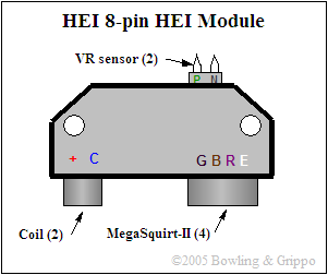
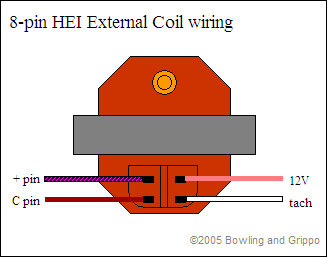
(Note that the 7-pin HEI module also has two pins for the variable reluctor pick-up ([pin P] and [pin N]) as well as one each for the coil [pin C] and +12 volts [pin +] from the battery. Together with the spark timing signal [pin E], Ref (tach) [pin R], and crank override [pin B], there are 7 pins in total ).
Virtually any engine equipped with a variable reluctor distributor and a single coil can use the 7-pin HEI module to interface with your MicroSquirt® controller. These have the advantage of being cheap, widely available (in North America), and reliable. These are available as:
In addition to the module shown above, you can use the HEI 8-pin module from the "small cap" HEI distributor. This was used on 1987 through 1992 Camaro/Firebird Tuned Port Injection V8 engines, as well as 1987 to 1993 full size cars and 1987 to 1995 pick-up trucks, and V6 MPFI cars (such as the Fiero). It uses a remotely mounted coil (i.e., not in the cap), which is typically is bolted to the intake manifold. The distributors are used primarily on roller cam equipped engines. Note that the GM 8-pin HEI module is basically the same as the 7-pin, except there is one extra pin: the extra pin is 'G' and is used for a ground. The 8-pin module has two 'mushroom' style connectors. One has 2 pins, it is used for the coil. The other has 4 pins, and is used for the electronic timing control. The timing control wires are usually the same colors as described above for the 7-pin module.
You can buy the 8-pin module as:
The 4-wire connector to your MicroSquirt® controller can be bought as:
The two lead connector for the small cap module is the same as the recommended CLT sensor connector:
The VR pins can use 1/8" spade connectors.
There are four pins on the external coil used with the 8-pin HEI module. These are tied together in pairs (so you'll see zero resistance between them). One set of two is on the +12 V positive side (electrically), the other is on the negative side.
In OEM applications, if you look at the coil connections with the high tension terminal up and the two connectors on the bottom (with the iron core horizontal), that:
You should find about 0.4 Ohms between these two sets of pins (the coil's primary resistance).
For the OEM HEI coils, set the dwell to
If the amount of desired dwell is longer than the remaining amount of time available, the dwell time is shortened and the amount of time available is used (otherwise the timing would be increasingly delayed).
After installing the your MicroSquirt® controller and HEI, be sure to use a timing light to verify that your 'trigger offset' is calibrated. Changing the Trigger Offset in TunerStudioMS will not change the displayed advance, instead, it changes the actual advance as seen with a timing light. Your goal is to make these two match.
To do this, get your engine warmed-up (otherwise the timing moves as the temperature increases) and idling, then use a timing light to verify to be certain your actual advance as shown by a timing light equals your the advance display on the advance gauge in TunerStudioMS. (Note that positive numbers denote BTDC, and negative numbers denote after TDC.)
The trigger offset value can theoretically be set anywhere physically, however, since it may be used for cranking and 'fault mode' timing (depending on how you have wired the bypass pin), it is best to set it at a reasonable number for cranking and idle, usually about ~8° BTDC (or whatever is recommended by the module's manufacturer). Check this with a timing light. To get the trigger offset to this value, you may have to physically rotate your distributor.
If you aren't sure where your trigger is physically located, you can set the trigger offset on your vehicle (with the 7 or 8 pin HEI module):
There are many more parameters to set up and tune to use the GM HEI effectively, see the: