V3 MicroSquirt® - QuickStart Guide
MicroSquirt® Coil Selection
MicroSquirt® Coil Selection
The MicroSquirt® allows the use of up to two coils in wasted spark or coil-per-cylinder set-ups. You may already have such coils, or you may want to retrofit some to your application. This document gives some hints as to what to look for, and what you will need to know.
Coil-On-Plug coils (COP) are typically used in overhead cam engines, especially 4 valve designs that allow for placing the spark plug in the center of the combustion chamber. Coil-on-plug designs can be 'pencil' coils or 'plug-top' coils:
Pencil coils are designed to take advantage of unused space typically found above a conventional spark plug (spark well). Their compact size enables them to fit directly into any typical spark plug hole (greater than 23 mm inside diameter) of four-valve dual overhead cam (DOHC) engines. Pencil coils are available in a variety of configurations and they can be found with outside diameters ranging from 22 mm to 29 mm, and energy rates from 35 milliJoules (mJ) to 80 mJ, depending on the coil size.
Plug top coils are designed to be used when packaging constraints prevent the use of pencil coils (spark well inside diameter less than 22 mm) and when a high output energy coil is required (energy >80 milliJoules). Secondary output energy ranges between 35 mJ and 100 mJ, depending on coil size.
Coil-Near-Plug coils (CNP) are typically used in overhead valve engine applications in which the spark plugs are located close to the exhaust manifold. An example is Chevrolet's LS1 coil-near-plug system. A coil-on-plug in this location would experience extreme temperatures (and would also make the engine much wider). Coil-near-plugs are connected to the spark plugs via short spark plug 'high tension' wires, which allows them to be displaced away from the hot manifold, in a location that doesn't add much to the overall engine size. They feature one coil per cylinder and are can be found with or without integrated igniters. Those without igniters need a high current drain from the ECU to sink the coil's primary current (along with high voltage protection on the drain). Those with igniters have separate +12V primary supplies and grounds, and the ECU need only control a low voltage 'TTL' signal to the coil (typically 5 Volts).
Wasted spark systems provide one coil per pair of cylinders. An example is Ford's EDIS system. Each coil has two high-voltage terminals, and these are connected to complimentary cylinders (those 360 degrees apart in the firing order). Wasted spark requires two coils for 4-cylinder engines; 3 coils for 6-cylinder engines, and 4 coils for 8 cylinder engines, those these are often packaged into 'coil packs' of two or three coils each.
In using any type of coil, you will need to establish a few things:
Starting in 1997, General Motors used a new (for them) coil-near-plug ignition system for the then new Corvette LS1 engine. The system features eight coils (one per cylinder) mounted on the valve cover, with short spark plug wires to connect the coils to the spark plugs. The General Motors LS1 coils are not just conventional ignition coils. Instead they are complete single-cylinder ignition systems. They contain all the electronics for dwell limiting, current limiting, etc. These coils are controlled directly by a low voltage, low current signal from the sequencer. There is no intervening ignition module (like an EDIS or GM DIS). Because the LS1 coils have the igniters built in, they make for an easy installation and generate less electromagnetic noise in the other wiring under the hood.
The LS1 coil has 4 connections (as well as the high tension terminal for the spark plug wire, of course):
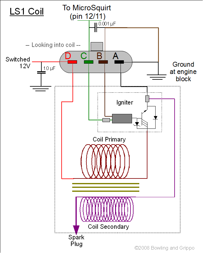
The two capacitors are optional but recommended. The 1.0 µF capacitor on the +12V is helpful, it is similar to the one used on EDIS. What it does is provide brief energy storage for the discharge. The other capacitor will help eliminate back-fed noise to your MicroSquirt® controller. Use a 100 pF to 0.001 µF cap on the TTL trigger input wire to ground. What this does is shunt extremely fast noise spikes to ground and not let them feed back to the MicroSquirt® processor. The added capacitance is minimal - with the series resistance of 1,000 ohms (in the controller) and a 100 pF cap the RC 3dB time constant is 2 * π * R * C = 0.6 microseconds.
These coils are used on late model Corvettes, Camaros, Firebirds, and GM trucks. The coils can be found as GM part number 12558948 (AC Delco D577), and can be found for around $20 each on the Internet or eBay.
You may also want:
The factory installation mounts the coils on the valve covers (4 coils on each valve cover). You may want to duplicate this set-up. On the driver side valve cover you can attach four ¼”-20 x 1” bolts through the stock valve cover (with the hex head inside the valve cover and a nut holding it in place from the top). Then use the threaded portion sticking up to mount the GM coil mounting bracket to the valve cover. Each of the coils can then be mounted using the GM mounting bracket (12562864). Your passenger side valve cover may have an oil fill cap and fresh air inlet for the PVC system which might interfere with the GM mounting bracket. So instead of the GM mounting bracket, you can use ½” x ½” steel tubing as a mounting rails for the passenger side valve cover. ¼”-20 x 1” bolts and nuts can be attached to the tubing for mounting the coils. Carefully locate the bolts so that the coils do not interfere with the oil fill and breather hole. The coils were then attached to the studs.
If you do not mount the coils on the valve cover, take care to put them where:
The LS1 built in coil igniters (the amplifier that drives the coil's primary current based on the sequencer signal) will follow the sequencer signal pulse width. When the signal from the sequencer is high (3 to 5+ Volts - with very little current from the controller, a few dozen milliAmps), the coil current will be building. When the signal from the sequencer is pulled low (shut off), the coil will spark. The duration of the signal from your MicroSquirt® controller determines the dwell (though the coil igniter limits this to no more than ~8 milliseconds).
As the dwell time increases, the peak coil charge current increases. The coil output current is not as linear. The LS1 coils do not fully saturate until around 8 milliseconds, but the spark energy does not increase much when the dwell exceeds 6 milliseconds. So stick with a 'running' dwell setting near the design value of 5.6 to 5.8 milliseconds. This will keep the coils cooler and extend their life. Note that MicroSquirt® uses a nominal dwell setting, called the 'maximum dwell', at 12.0 Volts and adjusts this for the continuously measured running voltage (since higher voltages charge the coil more quickly, the dwell is shortened, and conversely, low cranking voltages need extended dwells to properly charge the coil for easy starting).
To get 5.6 milliseconds of running dwell, the nominal dwell parameters should be set to:
| Maximum Dwell | 6.1 milliseconds | |
| Maximum Spark Duration | 2.0 milliseconds | |
| Acceleration Compensation | 0.6 milliseconds | |
| Battery Voltage Compensation | ||
| Setting | Net Voltage | Dwell Compensation |
| -4.0 | 8.0 Volts | 2.4 milliseconds |
| -2.0 | 10.0 Volts | 0.9 milliseconds |
| 0.0 | 12.0 Volts | 0.0 milliseconds |
| 2.0 | 14.0 Volts | -0.5 milliseconds |
| 4.0 | 16.0 Volts | -0.9 milliseconds |
This will give 6.1 - 0.5 = 5.6 milliseconds at 14.0 volts while running with the alternator charging normally. There is lots more information on setting dwell here: Setting Dwell.
The LS2 coil-near-plug coils are similar in form and function to the LS1 coils described above. This 'family' of coils includes:
These LS2 coils are incredible. Even compared to the LS1 coil, these are just crushers! On the LS1 coil there is around 40 milliamps of peak secondary current with 5 milliseconds of dwell time. On the LS2/truck coil (AC Delco D585), there is 120 milliamps!
We will call the second coil type the LS2/truck coil. These two types of coil have the same connector and pin-out, but the physical mounting pattern is different. The coil connector (GM# 12580353) can be found as:
There are plenty of either these coils on eBay, and they often sell for around $22 each at the time this is written.
The LS2 coil has 4 connections (as well as the high tension terminal for the spark plug wire, of course):
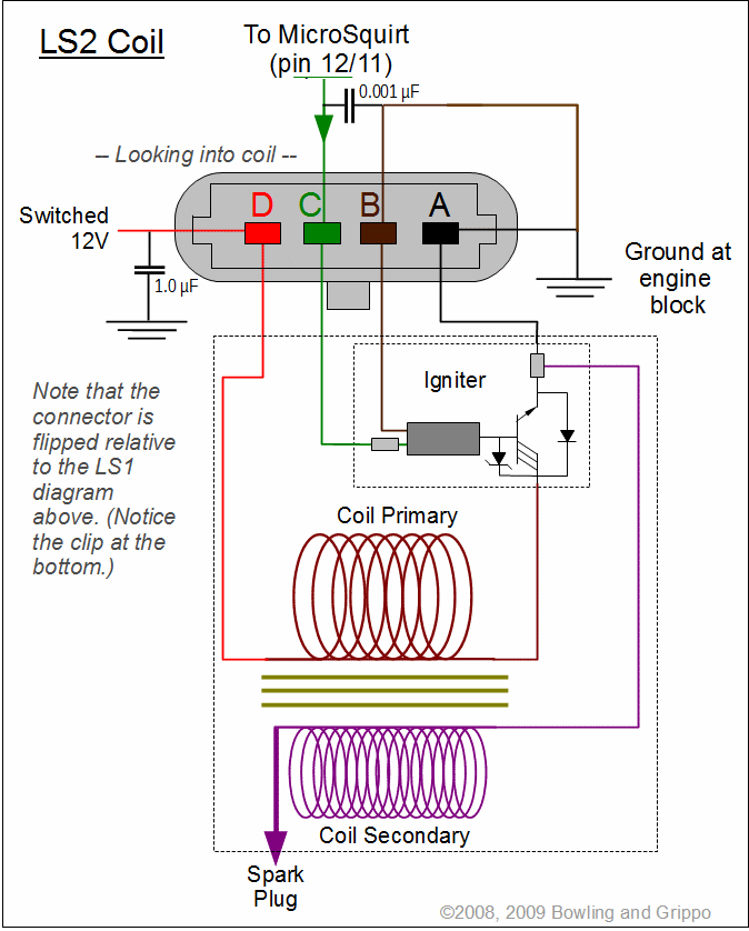
The two capacitors are optional but recommended. The 1.0 µF capacitor on the +12V is helpful, it is similar to the one used on EDIS. What it does is provide brief energy storage for the discharge. The other capacitor will help eliminate back-fed noise to the MicroSquirt® controller. Use a 100 pF to 0.001 µF cap on the TTL trigger input wire to ground. What this does is shunt extremely fast noise spikes to ground and not let them feed back to the MicroSquirt® processor. The added capacitance is minimal - with the series resistance of 1000 Ohms (in the controller) and a 100 pF capacitor the RC 3dB time constant is 2πR × C = 0.6 microseconds.
The LS2 built in coil igniters (the amplifier that drives the coil's primary current based on the sequencer signal) will follow the sequencer signal pulse width. When the signal from the sequencer is high (3 to 5+ Volts - with very little current from the controller, a few dozen milliAmps), the coil current will be building. When the signal from the sequencer is pulled low (shut off), the coil will spark. The duration of the signal from the sequencer determines the dwell (though the coil igniter limits this to no more than ~8 milliseconds).
The maximum dwell should be set at 4.5 milliseconds - going longer does not generate any more spark energy.
To get 4.0 milliseconds of running dwell, the nominal dwell parameters should be set to:
| Maximum Dwell | 4.5 milliseconds | |
| Maximum Spark Duration | 2.0 milliseconds | |
| Acceleration Compensation | 0.5 milliseconds | |
| Battery Voltage Compensation | ||
| Setting | Net Voltage | Dwell Compensation |
| -3.0 | 8.0 Volts | 2.4 milliseconds |
| -1.0 | 10.0 Volts | 0.9 milliseconds |
| 0.0 | 12.0 Volts | 0.0 milliseconds |
| 0.5 | 14.0 Volts | -0.5 milliseconds |
| 1.0 | 16.0 Volts | -0.9 milliseconds |
This will give 4.5 - 0.5 = 4.0 milliseconds at 14.0 volts while running with the alternator charging normally. There is lots more information on setting dwell here: Setting Dwell.
Here is a video of the coil in action - with the LS1 on the test stand you can hear the sparking, not loud but certainly audible. With the LS2/truck coil it sounds like someone is banging on the table! The big resistor you see in the video is part of a voltage divider setup. Its value is 100 megaohm (R1), in series with a 100 Kohm (R2), this pair is across the spark plug. The voltage across the 100 Kohm resistor is what is viewed on the scope.
The voltage on the scope is:
Vscope = Vsecondary * (100K/(100meg+100K))
You can find big value resistors often on eBay. Tesla Coil builders use these for high voltage measurements, so there is enough demand for such devices that they are fairly common.
You could use a oscilloscope high-voltage probe instead. These are nothing more than a voltage divider as described above. You can find these on eBay, etc. for next to nothing. They were popular for measuring the flyback voltage on old black&white televisions, radar oscilloscopes, etc. These days the demand for high voltage probes is pretty low. But for anyone here on this list reading this, a high-voltage probe is all but essential. We recommend a Tektronix P6013A probe if you ever stumble across it at a hamfest or on eBay.
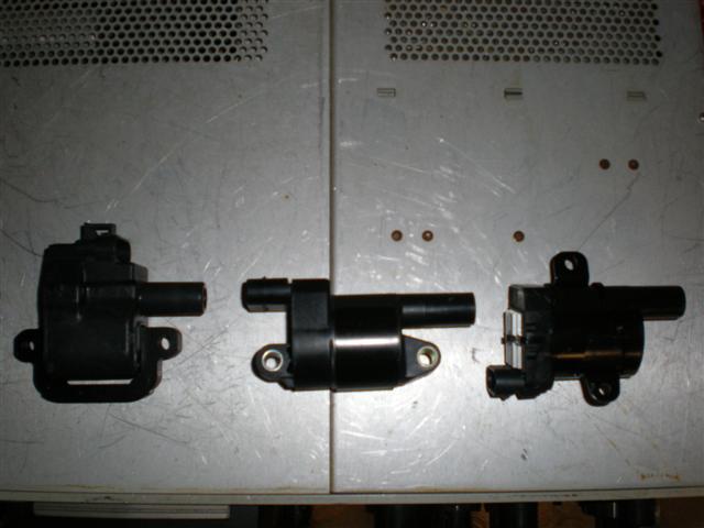
Here are some scope shots, first is what the three coils look like (on the left is an LS1 coil, in the middle is an LS2 coil, and on the right is an LS2/truck coil - you can see the aluminum heat sink on the LS2/truck coil):
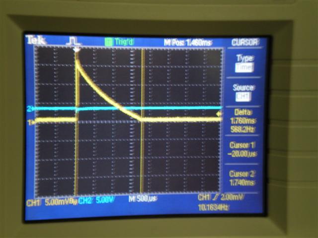
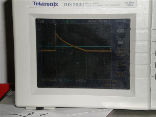
Here is the current measurement trace for the LS2 coil - the two yellow vertical lines are the measurement cursor and the time is listed under the "Delta" label on the right on the scope face:
Here is the current measurement for the LS2/truck coil:
There are several ways to measure the secondary voltage, but a surprisingly simple and accurate way is to use two spheres and increase the gap until there is no spark, this will yield the peak voltage. Out tests were run using two 2.5cm (1") ball bearings that are set up so we can increase the gap until the spark stops, then measure the distance.
Air normally acts as a good insulator (or dielectric). However, when the voltage across an air gap becomes sufficiently high, electrons are stripped from the air molecules, ionizing the air and allowing current to flow. This is what is happening when lightning strikes during a thunderstorm. The process is called dielectric breakdown, and the voltage at which it occurs is the dielectric breakdown voltage. The dielectric breakdown voltage for air is approximately 3300 kiloVolts/centimeter, but also depends on other factors such as the geometry of the gap and the air pressure.
In the old days (1940s!) the CRC handbook had all sorts of useful charts and figures, the newer book revisions do not have this fun stuff. Here is a chart found on www.pupman.com (a Tesla coil site, in the forums) for determining spark voltage from sphere distance, pulled from a 1955 CRC handbook:
Gap for Spark, by Voltage
Based on results of the American Institute of Electrical Engineers Air at 760 mm, 25° Celsius | |||||
| Peak Voltage kiloVolts | Gap (centimeters) | ||||
| Diameter of spherical electrodes, cm | Needle Points | ||||
| 2.5 | 5 | 10 | 25 | ||
| 5 | 0.13 | 0.15 | 0.15 | 0.16 | 0.42 |
| 10 | 0.27 | 0.29 | 0.30 | 0.32 | 0.85 |
| 15 | 0.42 | 0.44 | 0.46 | 0.48 | 1.30 |
| 20 | 0.58 | 0.60 | 0.62 | 0.64 | 1.75 |
| 25 | 0.76 | 0.77 | 0.78 | 0.81 | 2.20 |
| 30 | 0.95 | 0.94 | 0.95 | 0.98 | 2.69 |
| 35 | 1.17 | 1.12 | 1.12 | 1.15 | 3.20 |
| 40 | 1.41 | 1.30 | 1.29 | 1.32 | 3.81 |
| 45 | 1.68 | 1.50 | 1.47 | 1.49 | 4.49 |
| 50 | 2.00 | 1.71 | 1.65 | 1.66 | 5.20 |
| 60 | 2.82 | 2.17 | 2.02 | 2.01 | 6.81 |
| 70 | 4.05 | 2.68 | 2.42 | 2.37 | 8.81 |
| 80 | --- | 3.26 | 2.84 | 2.74 | 11.10 |
| 90 | --- | 3.94 | 3.28 | 3.11 | 13.30 |
| 100 | --- | 4.77 | 3.75 | 3.49 | 15.50 |
| 110 | --- | 5.79 | 4.25 | 3.88 | 17.70 |
| 120 | --- | 7.07 | 4.78 | 4.28 | 19.80 |
| 130 | --- | --- | 5.35 | 4.69 | 22.00 |
| 140 | --- | --- | 5.97 | 5.10 | 24.10 |
| 150 | --- | --- | 6.64 | 5.52 | 26.10 |
| 160 | --- | --- | 7.37 | 5.95 | 28.10 |
| 170 | --- | --- | 8.16 | 6.39 | 30.10 |
| 180 | --- | --- | 9.03 | 6.84 | 32.00 |
| 190 | --- | --- | 10.00 | 7.30 | 33.90 |
| 200 | --- | --- | 11.10 | 7.76 | 35.70 |
| 210 | --- | --- | 12.30 | 8.24 | 37.60 |
| 220 | --- | --- | 13.70 | 8.73 | 39.50 |
| 230 | --- | --- | 15.30 | 9.24 | 41.40 |
| 240 | --- | --- | --- | 9.76 | 43.30 |
| 250 | --- | --- | --- | 10.30 | 45.20 |
| 300 | --- | --- | --- | 13.30 | 54.70 |
For determining the effects of gas pressure on the required spark gap, there is an SAE paper, number 2000-01-0245, entitled "Ignition System Measurement Techniques and Correlations for Breakdown and Arc Voltages and Currents" where the authors performed extensive testing with respect to gas pressure, electrode spacing, and flow.
They compared their measured data to a well-known expression known as "Paschen's Law" relating spark gap to pressure and potential, and performed a little tweaking on the constants and created a linear model. The relation published in the paper for gas composition air is (this equation is also in the IgnitionCoilAnalyzer program):
V = 4.3 + 136 × (p / T) + 324 × (p / T) × Dg
The temperature after compression (before combustion) is:
Tcompressed / Tinlet = (Vcompressed/Vinlet)(γ - 1/γ)
where:
The pressure after compression is:
Pcompressed / Pinlet = (Vinlet/Vcompressed)γ
where:
Here is a calculator that combines these equations. Plug in your gap, intake pressure, compression ratio, etc., then click outside the text boxes, and determine the theoretical voltage needed to initiate gap breakdown (note that we have changed the units to be more conventional):
|
Breakdown (ionization) Volts
|