With the upgrade to Version 3, your MicroSquirt® controller's the Variable Reluctance (VR) interface circuit has been changed to a new circuit using the Maxim MAX992x integrated circuit. This interface circuit offers an adaptive triggering threshold for VR sensors, and can be used to interface directly to Hall sensor arrangements.
Here is a block diagram of the new VR interface:
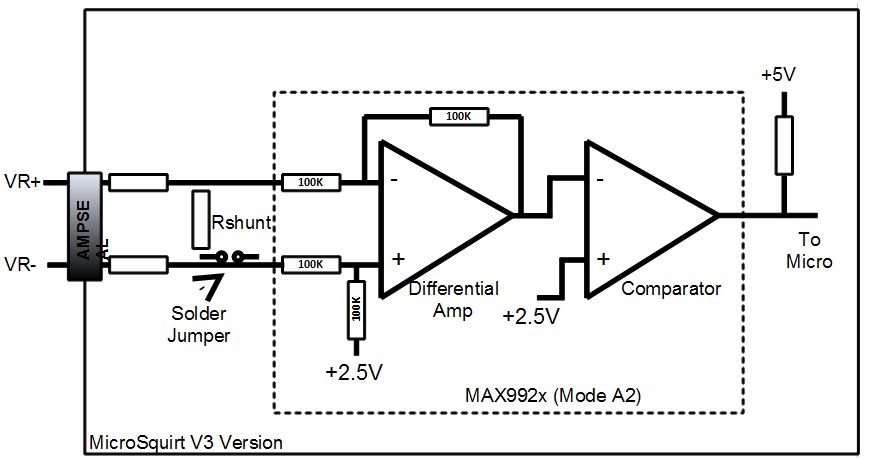
The circuit operates as a differential amplifier followed by a comparator section. Note that the circuit overall is an level inverting setup (due to the comparator stage). The previous generations of MicroSquirt® controllers used non-inverting VR amplifier implementation. To keep compatibility, the signal inputs VR+ and VR- (on the MicroSquirt® AMPSEAL) connect to the (-) and (+) inputs on the MAX992x differential amplifier respectively, see the figure. In other words, the VR+ AMPSEAL input connects to the inverting (-) input on the MAX992x, and the VR- connects to the non-inverting (+) input. This connection method is of no real consequence to the user, in fact it makes the use of the circuit more straight-forward.
With the new VR interface on the V3 MicroSquirt® controller, there are a few items to keep in mind when interfacing to VR or Hall sensors. The first thing to keep in mind is that the new circuit detects voltage levels between two inputs (VR+ and VR-). The new VR interface circuit brings out both of these out to AMPSEAL pins, and for both VR channels (Crank and CAM). So, it is important to use both inputs when interfacing to a VR sensor.
Second, on the previous MicroSquirt® controller's VR sensor interface, the circuit was ground-referenced, meaning that the return path from the VR sensor is at 0 volts potential (or ground level). With the new interface circuit on MicroSquirt® V3, the VR- input has a weak pull-up voltage applied at 2.5 volts thru an internal resistor connected to the differential amp on the MAX992x (see the figure above). Also, the MAX992x comparator (+) input has 2.5 volts as well - this voltage will automatically adjust depending on the current adaptive mode but is centered around 2.5V. So, it is important to connect both VR sensor wires to the VR+ and VR- input. Also, make sure that there is no internal connection of the VR sensor to ground - use a multimeter in resistance measurement mode to make sure. The majority of VR sensor signals are floating and do not connect to ground.
The MAX992x circuit threshold will adapt to the input signal amplitude in order to produce a variable adaptive threshold to reject noise and false teeth triggers. However, the voltage input range to the circuit is 0 to 5 volts, voltages outside of this range are clamped to the voltage supply rails using internal body diodes. However, some high output unloaded VR sensors can easily generate voltages in excess of 100 volts or more - this voltage range is clamped to 0 and 5 volts by the MAX992x. This is good - however note that the adaptive range is now also clamped as well, while the false teeth amplitudes are scaled by the VR voltage and can cause false triggers. In this case, adding a shunt resistor across the VR sensor will reduce the VR voltage overall and allow the adaptive mode to operate even at high RPMs. The MicroSquirt® controller V3 board has a solder jumper located on the bottom of the PCB that can be used to add a shunt resistor.
The input biasing in the MAX992x makes operation with Hall sensors easy, since the comparator level is at the ideal level - just connect the hall sensor to the VR+ input and leave the VR- input floating. You will need to use a pullup resistor for the Hall sensor, either to Vref or to +12V depending on the voltage range of the Hall sensor. Note - do not solder the Rshunt jumper pad on the bottom of the MicroSquirt® controller PCB - no shunt is required for Hall sensor. Also, for TTL signal triggering use the VR+ input for the signal and leave the VR- input unconnected.
Here is a quick table of the different operating modes and connections:
| Mode | Connection |
| Opto Input |
|
| VR Sensor |
|
| Hall Input |
|
V2/ V3 Wiring Harness Differences
The wire colors are the same as before. The only changes are the twisted pair wires for VR and VR2, and a new pin for VR2 (VR2 used to shared a pin with the other VR, now it's a balanced line and has its own pin).
Additional Wiring Tips
1) Make sure the serial return is on pin 19 (Ampseal) and the VR- return is on pin 33. These pin placements are not random - they actually have separate tracks that route directly back to their respective circuitry. If you look on the MicroSquirt® controller board on these pins you can see a track on each of these pins - one goes up to the serial chip, the other goes over to the right side of the board. So these pins need to be correct
2) For the previous MicroSquirt® controller versions that use the V3 input circuit setup, the cable needs to be coaxial with the shield being the VR- return - this is what was shipped with the harness. Coax is correct for this because it is a single-ended, ground-referenced circuit (unbalanced). With the new V3 MicroSquirt® controller version, it needs to use shielded twisted pair for the MAX992x chip because this is a true balanced line differential input and it can actually benefit from this. This is the harness that will ship with the production V3 version.
3) Make sure that the sensor harness is grounded back at the pin 20 Ampseal, and nowhere else. This means the TPS, coolant, MAP, IAT grounds come back to this wire. The sensor return grounds internally in you MicroSquirt® controller, but if there is an external ground connection as well on this there is an instant ground loop. Recently one person had a noise issue. We had them unplug the Ampseal and check the resistance from the harness-side Ampseal pin 20 and vehicle ground. With the Ampseal unplugged there should be a few K resistance or higher - if it reads near zero ohms then the sensor wire is grounded somewhere. He tracked down this erroneous ground connection, and once it was removed all noise went away.