Your MicroSquirt® controller uses two negative temperature coefficient thermistors to determine the coolant and air temperatures. Thermistors are resistors whose resistance changes with temperature. Negative temperature coefficient means the thermistor's resistance decreases as the temperature rises:
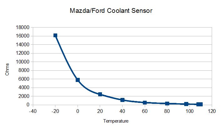
An example is the Ford/Mazda (used in the MX-6 and Ford Probe GT, for example) coolant temperature sensor. Its resistance curve is:
Resistance (Ohms) | °F | °C |
| 16150 Ω | -4°F | -20C |
| 5800 Ω | 32°F | 0C |
| 2450 Ω (range 2200 to 2700 Ω) | 68°F | 20C |
| 1150 Ω | 104°F | 40C |
| 550 Ω (range 400 to 700 Ω) | 140°F | 60C |
| 320 Ω (range 290 to 350 Ω) | 176°F | 80C |
| 199 Ω (range 193 to 205 Ω) | 207°F | 97C |
| 149 Ω (range 145 to 153 Ω) | 226°F | 108C |
| 141 Ω (range 137 to 145 Ω) | 230°F | 110C |
Your MicroSquirt® controller uses coolant and air temperature sensors to determine the warm-up characteristics of the engine and the density of the intake air. They are essential to proper functioning of your MicroSquirt® controller. Both sensors are Negative Temperature Coefficient (NTC) thermistors. This means that they are resistors whose resistance decreases as their temperature goes up.
Your MicroSquirt® controller uses the temperature sensor as one leg of a voltage divider. 5.00 Volts (we will call this Vs) is supplied to a default 2,490 Ohm (2.49K Ohm) resistor (called a "bias resistor", and we will denote it as Rb) and this resistor is connected to the temperature sensor (denoted here by Rs) which in turn is connected to ground.
The voltage between the two resistors is:
Resistor Rp does not affect the voltage divider, it simply limits the current to the processor pin (there should be very little current anyhow, the input is "high impedance").
Your MicroSquirt® controller reads this voltage as a series of voltage steps: 1023 0.005 Volt steps. The conversion from volts to steps is done by the analog-to-digital converter (ADC).
The general relationship between the temperature of the thermistor and its resistance is given by the Steinhart-Hart equation1. The Steinhart-Hart equation relating the resistance to the temperature of a thermistor is:
and the temperature T is in Kelvin (= Celsius + 273.15°) and the thermistor resistance Rs is in Ohms. 'ln()' is the natural logarithm function.
When you enter three temperature/resistance pairs into TunerStudioMS to calibrate the coolant or intake air temperature sensors, TunerStudioMS uses those pars to determine the Steinhart-Hart coefficients, which it then uses to calculate 1024 elements of your MicroSquirt® controller's internal table, very similarly to how the following calculator does it:
The Steinhart-Hart thermistor equation1 coefficients for the example Ford/Mazda sensor above are:
Here is a calculator to see the temperature/resistance pairs with the Steinhart-Hart equation (the default coefficients are as above):
You can also get the resistance for a given temperature. The easiest way to do this is to use the 'βeta model' of the thermistor, which is:
and R25C is the resistance at 25C, and β is a constant.
For the Mazda sensor, β is equal to 3536, and the resistance at 25C is 1959Ω. Here is a calculator that uses the β equation to get resistance from the entered temperature.
For example, we would expect the resistance at -40° to be about 54K Ohms.