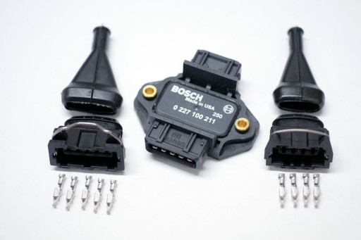
For four-cylinder applications using a MicroSquirt® controller with 4 COP (coil-on-plug) coils, an excellent ignition driving solution is the Bosch 0 227 100 211 4-channel igniter. (Note that you cannot 'direct drive' more than two coils independently with MicroSquirt® EFI controller, but you can drive up to 4 coils in 'wasted spark' mode; see: MicroSquirt® Direct Coil Control)
The module's datasheet is here: Bosch 0 227 100 211 datasheet (~700kB)
This module will directly drive four individual induction ignition coils. The module is particularly useful for motorcycle and ATV setups where space is at a premium.
The Bosch 0 227 100 211 'igniter' module (called the "Bosch 211" here) is not a 'smart' module. That is, it DOES NOT control dwell. Because of this, we need to use the settings in MegaSquirt-II to set the dwell, etc. However, it also means that the module can be used with a variety of coils by setting the dwell appropriately (unlike an EDIS module, for example).
The Bosch 211 fires the coil when the ignition signal from the MegaSquirt-II/MicroSquirt® controller goes from high to low. In TunerStudio, you would set:
Parameter | Value |
| Ignition Input Capture | Falling Edge |
| Cranking trigger | Trigger Rise |
| Coil Charging Scheme | Standard Coil Charge |
| Spark Output | Going High (Inverted) (for logic-level MicroSquirt® mods) |
The Bosch 0 227 100 211 module is particularly useful in that it provides direct drive to four ignition coils from logic-level input drive. Each channel of the module can handle around 5 amps of coil primary current, impressive for its small size. The MicroSquirt® needs to be configured to provide a logic-level signal of 0 and +5 volts to the four input channels. When an input channel is at a logic 1 (5 volts) the corresponding channel coil will see a charging current for the dwell period. When the input signal transitions from 5 to 0 volts the corresponding channel coil will spark.
Since MicroSquirt® has only two ignition output channels, for 4-cylinder applications the module needs to be wired in wasted-spark configuration. This is accomplished by hooking two input channels together to make a single wasted spark channel - this is performed twice to make two separate wasted-spark channels. On the module, connect the input channels IN1 and IN3 together to form one channel, and IN2 and IN4 together to form the second channel.
Connect:
The coils above are wired such that coils 1 and 3 will fire together, and coils 2 and 4 will fire together. You need to wire the coils in the firing order required for your engine.
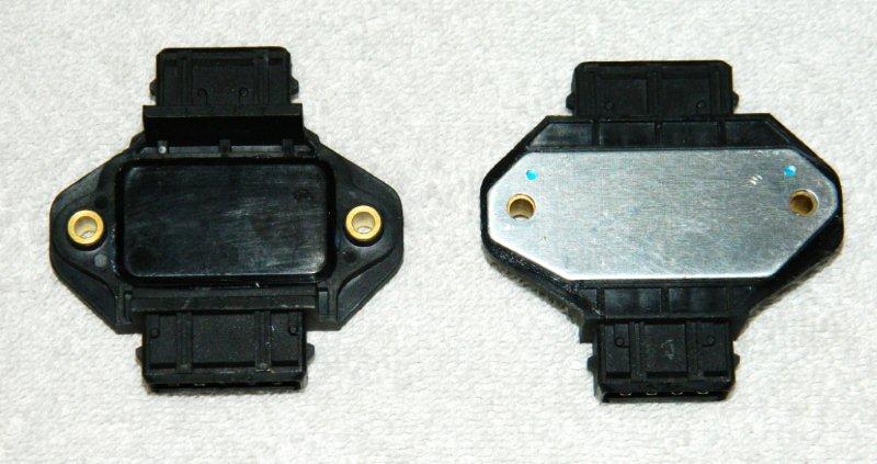
The Bosch 211 module needs to be mounted on an aluminum heat sink which is grounded (to the same ground as the GND terminal on the module). This ground return path is for both the primary circuit charging and the secondary coil return path. A connection wire direct to the engine block is usually sufficient.
The MicroSquirt® hardware needs to be configured to provide a logic-level signal output in order to properly drive this module, there are details on this is here.
Here are some common part numbers that different suppliers use for the Bosch 211 module (or its exact replacements):
| Bosch | 0 227 100 211 1 227 100 212 |
| Audi | 4D 0905 351 |
| Beru | 0040401028 |
| Lucas | DAJ124 |
| Magneti-Marelli | 940 038 536 |
| Huco | 13 8055 |
| Hella | 5DA 006623771 |
| Hitachi | DIS408 |
The following is a list of some of the vehicles which have used the Bosch 211 (or its replacements) as original equipment. This may help if you are looking in a junkyard, or if you need to source one from a parts store and they require an application to look the part up.
| Audi A4 1.8L Turbo | 1997-2001 |
| Audi A4 Quattro 1.8L Turbo | 1997-2001 |
| Audi A8 | 1998-1999 |
| Audi A8 Quattro | 1997-1999 |
| Volkswagen Beetle | 1999-2001 |
| Volkswagen Passat | 1998-2001 |
| Volkswagen Jetta | 2000-2002 |
| Volkswagen Golf | 2000-2002 |
The 211 module must be mounted on a heat sink (w/ thermal grease in between). OEM installations often locate the module on a heat sink that protrudes into the air intake, ensuring that the heat sink is actively cooled whenever the engine is running. The module can be attached using its two 4.5mm (3/16") mounting holes spaced 54mm (2.125") apart.
The 211 module uses connectors 1 287 013 900 and 1 287 013 006.